French Trench Construction Methods
Background for French Trench Construction Methods
While there are certain universals regarding the construction of field fortification, French positions were unique from those of its allies. The subject of French army entrenchments can not be studied without viewing it in the context of the mindset of the État-Major ("High-Command"), which rested entirely on the notion of offense, both on the strategic and tactical levels. In addition, the lack of construction materials also played a significant factor.
Many generals, particularly the most senior commanders, refused to accept the fundamental reality of the war that came about with the first trench systems in the fall and winter of 1914. To them, trench warfare was simply a transitional stage of the war which would eventually be broken with the transition back to open warfare. This view was reinforced with the fact that France had been invaded and French sacred soil under German occupation. On the tactical level, French army doctrine of the time emphasized the offensive solely. The État-Major feared that if their men were permitted to dig deep, formidable entrenchments, a bunker-mentality would develop. The men would lose their offensive-spirit and become content to stay where they were. This was something that had to be absolutely avoided.
Following this line of thought, the État-Major saw no reason to invest a significant amount of time and resources in the training of entrenchment techniques or construction supplies before the war. Only the génies ("engineers") were given this specialized instruction and there were far too few of these units. Instead the men applied the knowledge of craft that many men possessed from their farming backgrounds. This helps to explain the governing force over all trench construction and indeed the French army as a whole: System D. The 'D' came from the verb débrouiller ("to muddle through") as it appears in the context of the phrase "on se débrouillera toujours" ("we'll always muddle through"). Under this system, problems which could not sort themselves out were resolved through improvisation. Ironically, this marks one of the greatest virtues of the French soldier. And it was reflected manifestly in the patchwork appearance of French positions; arguably more so than those seen in the British or German lines.
They involved a combination of various types of trench revetments used in conjunction with each other. And of course, the absence of any revetment was also a common site in French trenches. Common revetting techniques included the employment of wattling, sandbags, chicken-wire, logs and planks. The most frequently used form of clayonnage ("wattling") in the French trenches included wattles, gabions and fascines.
Revetments with Clayonnage
The following are the average dimensions of wood used in making the various forms of clayonnage:
Sticks:
For fascines..........................length - 9 ft., diameter - .75-1 in.
For claies and gabions...........length - 9 ft., diameter - .5-.75 in.
Stakes:
For claies and gabions...........length - 3.6 ft., diameter - 1 in.
&nsp Small...........................length - 1.5-1.8, diameter - 1 in.
&bnsp Large...........................length - 1.8-2.9 ft., diameter - 1-2 in.
Claie:
A claie ("wattle" or "hurdle") was rectangular in shape and composed of an interlaced panel of sticks woven between vertical stakes. Sometimes they were made with supplied, finely woven wickerwork. They varied from 6.5-7 feet long and 2.5-3 feet high. It typically weighed 30-45 lbs. Normally, these were constructed in place, right into the wall of the trench. However, they could also be constructed in the rear and then carried up to the trenches.
Gabion:A gabion ("gabion") was a cylindrical, bottomless basket composed identically to a claie. Typically a gabion was about 3 feet high and 2 feet in diameter, weighing about 40-50 lbs. They were normally made in the rear and carried up to the trenches. When digging proved more difficult, such as in particularly wet or rocky soil, gabions were more often employed. They were constructed in the rear and then carried up to the trenches.
Fascine:A fascine ("fascine") was a long cylindrical bundle of sticks fastened together with thin switches or iron wire. Fascines were about 8 feet in length and 8-12 inches in diameter. They usually weighed 35-40 lbs. Again, when digging proved more difficult, such as in particularly wet or rocky soil, fascines were more often employed. They were constructed in the rear and then carried up to the trenches.
Materials
The best choice of tree to use in the construction of clayonnage is oak, yoke, elm, birch, hazel and chestnut. Willow and poplar can also be used. Pine trees can be used but are not as well suited for the purpose due to their stiffness. For the sticks used in clayonnage, saplings are preferable to branches. Binding twigs -- used for fastening together a fascine or the sticks to the stakes in the case of claies and gabions -- are chosen from the smallest and most flexible branches, and stripped of their off-shoots and leaves. Besides the kind of trees mentioned above, vine, tamarind, alder and oiser are all suitable to use for bindings.
Elements of the Clayonnage Revetments
Binding twigs are obtained by twisting the stick in one of the following manners:
- Place the butt end of the stick under the foot and twist it progressively with the right hand, beginning at the thin end, while at the same time holding the stick with the left hand and rolling it with the foot in proportion to the advancement.
- Place the thin end of the twig in a slot made near the end of a stake (4-6 inches in diameter) which is planted in the ground. Begin twisting the twig at the butt, holding it out extended and rolling it around the stake as the work progresses. The twig having been twisted up to within 7-12" from the butt of the stake, make a loop at the opposite end if there is room.
The stakes are made alternately from the strongest and straightest branches, young saplings, strong poles, or split wood. They are sharpened on the end by two cuts, usually at the thinner end. The work is usually accomplished by groups of two men, each equipped with 1 hand-saw, 1 hatchet and 1 bill-hook.
Construction of Claies
Personnel: Parties of three to four men, two to cut and place the wood and one or two to make and place the binding twigs.
Tools: Two pruning knives, 1 hatchet, 1 handsaw and 1 sledge hammer.
Materials (on average):
5-6 stakes, 80-100 sticks, 8 binding twigs
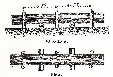
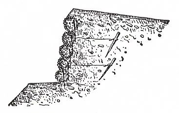
On a level patch of ground, trace with string a straight line a little over 7 feet long. Next, at one end of the string drive the first stake into the ground to a depth of 5-6 inches. Drive the following stakes into the ground at regular intervals along the string, on average 1.5-2 feet. Two men then stand at either end of the line of stakes and starting at the bottom, successively weave the sticks between the stakes in an alternating fashion. Alternate between placing the thinner end of one stick above the thicker end of the next, so that both sides are in proportion. The thin ended sticks that project past the outside stakes are cut, except for 5 or 6 on each side, which are twisted around the outside stakes in order to fasten them to the revetment. Four binding twigs are used on the corners of the claie and the other 4 being placed with 2 on top and 2 on the bottom, spaced equidistantly. (See figure above)
Construction of a Revetment of Claies
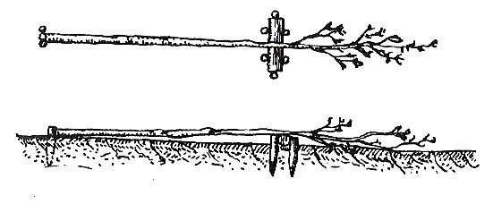
Claie ("wattle") revetments are usually constructed in place and sometimes made with supplied wickerwork. However, the claies can also be assembled sections in the rear and carried up to be put in place. Work parties of three men are formed. If possible, pegs (about a foot in length) are buried in the face of the slope, following the line of the slope. Two men drive the pegs and weave the hurdles as described above; the third man prepares the wood. As the revetment is gradually built up, the soil is filled in behind it and packed down. Place anchoring twigs at intervals, stretched between the stakes of the revetment and anchoring pegs located 6-10 feet in front.
Construction of a Revetment Using Branches
This type of revetment is less resistant than using claies but is more rapidly constructed. First, a row of pickets is placed along the face of the slope. Place anchoring twigs at intervals and nail a board onto the pickets a slight distance from the top ends. Fix into positions branches (1-2" in diameter), which are pressed together with the feet between the pickets and the soil, the branches resting directly on the face of the slope. The branches are not brought right up to the top of the pickets, but stopped a short distance from the ends. This revetment can be used to particular advantage in the covered communication trenches and in shelters. The branches are secured between the supports of the roof and the wall.
Alternately, heavier branches or thin logs (3-6" in diameter) could also be employed in this same manner.
Construction of Gabions
Personnel: Pairs of two men.
Tools: Two pruning knives, 1 mallet, 1 string (.95) inches long. Additionally, if iron wire is used, 1 pair of pliers, 1 pair of wire-cutters and 1 gimlet.
Materials (on average):
7 stakes, 80-100 sticks, 8 binding twigs
On a level patch of ground, trace with a string a circle about 21 inches in diameter. Next, drive in the stakes at 7 equidistant points along the string, about 8 inches apart, to a depth of 6 inches, the stakes being inclined slightly toward the interior. With the stakes set, two men place themselves at opposite sides of the circle of stakes and begin weaving simultaneously at the bottom, working around in the same direction. The large ends of the stick are placed on the inside and against the stakes. Each man works at the same time with two sticks, taking care to twist one around the other simultaneously as they pass around the stake. In order to ensure that a stick be neither too thin nor too thick, join its small ends with a new stick and continue to weave in such a manner that the butt end of each new stick is on the inside of one of the stakes. (See figure above)
The wickerwork having been woven up to a height of 2.9 feet is ended and 4 binding twigs are attached. Each binding twig ties together a stake and 5 or 6 strands. Alternately iron wire can be used. There are two different types of binding twigs: those with and those without loops.
Binding twigs with loops:
Pass the free end of the twig from the interior to the exterior of the wickerwork, alongside a stake, about 6 inches below the top edge of the wicker. Place the loop over the top of the stake and pull snugly on the twig. Then twist it slightly and pass the free end through the loop and around the top of the stake. Pass the free end two or three times between the twig and the wickerwork, twisting it toward the bottom to form a regular strand. Pass it around the stake and fasten it into the wickerwork. At the same time, the second man beats the twig with a mallet in order to fit it snugly against the stake and the wickerwork.
Binding twigs without loops:
Pass a binding twig half its length through the wickerwork, alongside a stake. Raise the two ends along the interior and exterior faces of the wickerwork and pass them around the stake above the top edge of the wickerwork. Wrap the ends of the binding twig around the stake, tying it firmly and fixing the twig in place with a mallet. Then pass each of the ends several times between the binding twig and the wickerwork in order to form a strand. Next, pass them through the wicker again and around the stake. Finally, tuck the ends into the wickerwork.
Binding with iron wire:
Drill a hole in the stake with a gimlet at the height of the fifth or sixth stick. Pass a wire (1.1 feet long) through the hole, with the end on the exterior of the wickerwork longer than the interior one. Make an opening in the stick at this point and a turn around the stake. Then bring this end together with the interior end and twist them together.
When the bindings are in position at the top of the stake, raise the gabion and turn it over. End the wickerwork near the point of the two stakes using 4 more bindings place on 3 stakes that have not yet been used and on a fourth, which subsequently has two bindings. Trim the gabion by cutting off the small twigs and shoots on the exterior but leaving those on the interior.
Construction of a Revetment of Gabions
Arrange the gabions side by side, tilting them in slightly in to conform to the face of the slope. Fill them in with earth and crown them, if necessary, with one or more rows of fascines so as to obtain the height of the slope being revetted. To reinforce the revetment, it is wise to anchor the gabions to pegs buried in the wall using rope or wire. Alternately, drive in some strong pegs on the inside of each gabion against the slope being revetted.
When the height of the slope being revetted is greater than 6 feet, two rows of gabions are placed on top of each other, with the first row allowing a crown of fascines to form a platform.
Construction of a Revetment of Flexible Gabions
An alternative to ordinary gabions (used when material is scarce) are flexible gabions, which are easily transported and put in place. Flexible gabions are composed of very thin planks (.4-.6 inches) nailed onto crosspieces of the same thickness. They are 32 inches long, 16 inches wide, and 18 inches high. They weigh about 18.5 lbs and can be folded up for transport. The hinges on a flexible gabion can be made in different ways.
Construction of Fascines
USING A HORSE
Personnel: Groups of 3-4 men, according to whether they use binding twigs, with or without loops. Two men to cut and place the wood and one or two men to make and place the binding twigs.
Tools: Two pruning knives, 1 hatchet, 1 sledge hammer, 1 mallet, 2 levers 5-6 feet long, 1 cord about 28 inches long (to serve as a measure of the circumference of the fascine); 1 capstan cord 4 feet long, with a loop; 1 pair of pliers and 1 pair of wire-cutters (if iron wire is used); 1 handsaw for sawing off the ends of the butts of the fascines.
Material: For each group - six stakes for fascine horses, 1 chopping block, and 9 short stakes for pegging down into the ground. For each fascine - one bundle of about 25 poles and 4-6 binding twigs.
First, organize the work yard by placing the chopping blocks as indicated in the figure below.
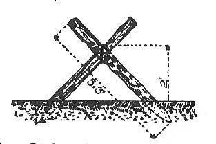
Plant three parallel horses, about 30 inches apart, the two stakes crossing each other at approximately right angles (see figure below).
- Preparation of the poles: One man strips the poles, straightens the crooked branches by cutting small notches with the pruning knife on the concave sides, and places them in front of a second man on his knees by the chopping block. This man cuts them to the proper length by placing the butts against three stakes driven into the ground at a proper distance from the block and cutting through the part of the pole which rests on the block using a pruning knife.
- Construction of the fascines: When there is enough wood to make several fascines, two men place a part of it on the horses, being careful to place the best branches on the outside and the slender ones in the middle, so as to form a fagot having a diameter slightly greater than that of the fascine. The men next compress the fagot with the aid of the levers and the capstan cord, so that the third man can verify it with the measuring cord. When the fascine is of the desired circumference, the third man places the binding twigs.
- Placing the twigs: The points for placing the twigs are indicated by notches on the pole at proper distances.
- Binding twigs with loops: The points for placing the twigs are indicated by notches on the pole at proper distances. Place the capstan chord about 2 inches from the place where the twig has been set. A man passes the twig around the fascine, passes the free end through the loop, pulls the twig firmly against the fascine using his foot to help him, bends the free end back on itself after having twisted it several times in the loop, and passes it several times between the twig and the fascine in such a way that the twist opposes that of the twig. Finally he forces the loose end into the body of the fascine.
- Binding twigs without loops: Turn back the two ends of the twigs on themselves so that they form a single knot. Two men then turn the ends opposite directions so as to bind the twig, which one strikes with a mallet several times. Each worker next pushes the ends between the twig and the fascine so as to form a twist, making doing so in the opposite direction as that of the twig. Then the ends are hidden in the body of the fascine. This method gives greater strength.
- Iron wire: Cut the wire beforehand into lengths of 2.7 inches. Pass the end under the fascine and turn the two ends back on themselves. Bring them back together, rolling them together, and bind them with pincers. Then stick the cuts into the fascine. Whatever type of bindings used, placed them so that the knots are in a line.
- Finishing work: Trim the fascines, cutting away the branches that are not properly bound in, and, if there is room, cut the ends off squarely. (See figure above)
WITHOUT A HORSE
Personnel: Pairs of two men.
Tools and Material: Same as above, save the stakes for the horses and with the addition of 6 short stakes.
First, organize the work yard by placing the chopping blocks as before (see figure above). Drive two rows of parallel stakes .84" and dig a ditch in the ground to help place the poles, or even better, place as indicated in the figure below, two blocks between the stakes.
The actual construction of the fascine is the same as above, with the exception of the following:
Fastening the poles: One of the two men binds the fascine by handling the two levers, while the other fastens the binding twigs. (See figure above)
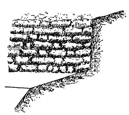
Construction of a Revetment of Fascines
Bury the first layer of fascines in the soil up to half their thickness. Secure each fascine using three pegs 24 inches long. Fill in the space behind the fascine up to its top, taking care to pack the soil down. Place a second layer of fascines so that the breaks fall at different points from the first layer and then secure it with pegs. At every 3 or 4 layers of fascines, and 5-6 feet apart, anchor the fascines to a peg buried in the wall of earth (about 6 feet in front) using rope or wire. Crown the revetment with a layer of sod. At the salient angles, saw off the ends of the fascines so that they are flush with the adjoining face. In the reentrant angles, bury the ends of the fascines of one of the faces into the soil.
Revetments of Various Materials
Construction of a Revetment of Sacs à Terre ("Sandbags")
Sandbags were used less often by the French than by their British counter-parts, mainly due to the lack of materials in the French army. However, they were still a staple material found in trench construction. While generally used in lining the tops of parapets or in the reinforcement of important positions such as observation and command posts, photographs show whole sections of trench also being entirely revetted with sandbags.
At the base of the revetment, make a small trench 20 inches wide and place therein the first layer of sandbags in an alternating fashion: either one sandbag placed lengthwise and the other widthwise, or, two placed width wise and one placed lengthwise. The sandbags of the next layer are placed off center from the first layer, so that the breaks are interspersed at different points. Take care to turn toward the side of the slope the openings of the perpendicular bags and to flatten them vigorously before using them. 10 and 9/10 feet of revetment requires approximately 23-24 sandbags, or 2 bags per 1 square foot.
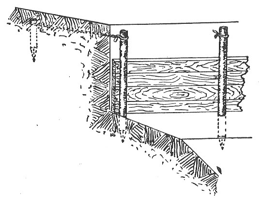
Construction of a Revetment of Planches ("Planks")
Place pickets in the plane of the slope at varying intervals according to the nature of the materials used (every 28" for planks, 20" for thin planks and boards). Place the planks against the inside of the pickets (between the pickets and the face of the slope), and fill the soil in behind them, packing it down gradually. Secure the pickets with anchoring stakes. Planks were used sporadically and parsimoniously in French trenches, again due to material shortages. Generally, they were reserved for shelters along with important positions such as observation and command posts.
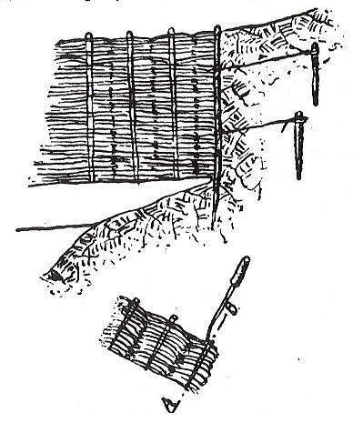
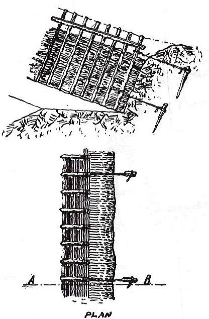
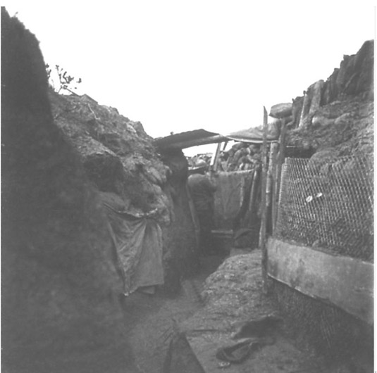
Construction of a Revetment with Treillage ("Chicken-Wire")
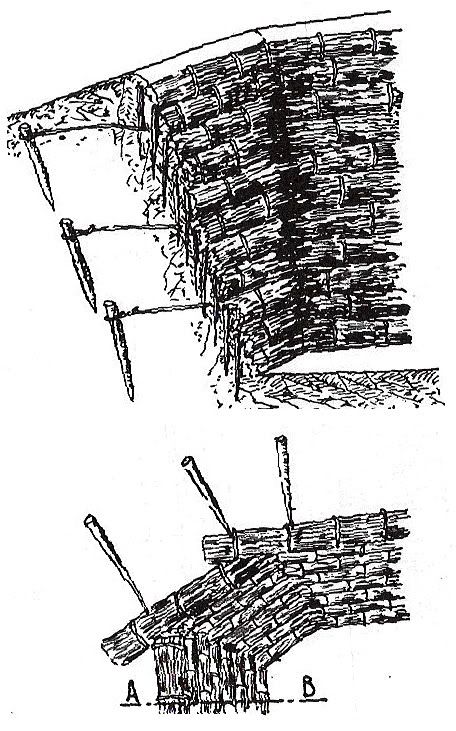
Treillage, or "metal latticework," of 1.2-1.6" mesh is preferred, composed of galvanized wire if available. If latticework or a greater mesh is used, the grillage is doubled by forming a double layer. Drive some pickets (2-2.4" in diameter) into the plane of the slope at intervals of about 6 feet, each held in place by an anchoring stake. Unroll along these pickets the coil of latticework, which is attached to the pickets by string or wire. Take care that two consecutive strips are joined together on a picket and cover each other by about 4 inches. Cut the coils in the angles of the slopes and fasten them to a stake driven along the line of intersection.
Pack down the soil of the parapet, taking care to place against the latticework the biggest clods or some small branches, grass or straw in order to avoid sifting of the soil. When the strip of latticework is not wide enough to cover the entire face of the slope to be revetted, place over it a second layer. If only a short distance is left to revet at the top, the revetment can be finished using soil or sod. (See right side of image below)
Construction of Créneaux ("Loop-holes")
Loop-holes are generally only used if the enemy can not discern whether they are manned or not. That is why by and large they are not to be used on the firing line that is in close proximity to the enemy. Use of loop-holes is reserved for observation posts and for well concealed, distant flanking trenches.
The exterior opening (i.e. the side facing the enemy) should be well concealed. This can be done in any manner of ways, though typically by a tight string netting stretched over the exterior frame of the loop-hole but which also affords the passage of the rifle barrel. The opening should not stand out silhouetted against the sky nor on a background contrasting with the color of the trench. Thus, the loop-hole must be laid level with the parapet. If necessary, the parados (back wall of the trench) must be heightened. It is recommended that a piece of cloth be stretched behind the rifleman's head, or other precautions taken to better reduce the visibility of the loop-hole and the man attending it.
If loop-holes have been installed, the direction in which they permit firing is one of the main concerns of the platoon leader in the trenches. He must examine them each in turn to be sure that the trench segment allotted to him fulfills the tactical purpose ascribed to it. Each rifle resting naturally on the floor of the loop-hole must be directed towards the zone to be swept and must assure a grazing fire along the ground, even at night when aiming is impossible. Furthermore, the platoon leader must frequently assure himself that the loop-hole has not risen slightly and that the rifle is not shooting too high.
All loop-holes have the same drawback: when the enemy gets to near, all firing must cease so as to get the rifles out of the loop-holes and bayonets fixed. Loop-holes are also destroyed by artillery fire. Therefore, the loop-hole is only used for "wearing down" fire. All devices should be prepared (firing-step raised between two loop-holes on logs, blocks, stools, sods, etc.) so as to check an attack by firing over the parapet, which is the only way to give a man the full advantage of his rifle.
Whenever possible (and such is generally the case with flanking fire) the loop-hole will be pointed obliquely in relation to the enemy trench opposite, so that the loop-hole becomes invisible and the rifleman keeps his head entirely protected. If the defenders are to fire a little off from the line perpendicular to the front it is recommended to prepare notches, which are simply grooves made for guiding the soldier's fire and to remind him not to shoot mechanically straight ahead.
Construction of a Poste d'Obsérvation ("Observation post")
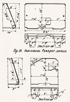
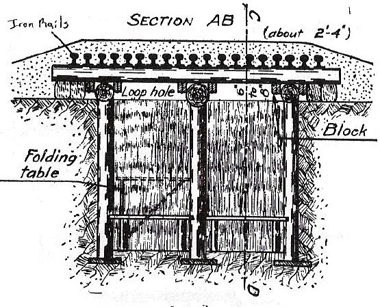
When time and materials were available, observation posts are reinforced, or armored, essentially becoming small sentry boxes built into the trench parapet (on the side closest to the enemy) big enough for one or two men. Sandbags, logs, planks, gravel and iron rails were all employed. Alternately, a less reinforced observation post may simply consist of a steel trench shield which is installed into the parapet. Again, these posts must be made to look as inconspicuous as possible. The first figure below gives an example of a simple observation post. Observation is made through a very narrow slit (perhaps only a few millimeters big) arranged between two rails, kept apart by small pieces of wood, which can be blocked when not in use.
Example of more heavily armored observation post which utilizes a front facing of sheet iron.
Reinforced observation post in wood.
Two examples of steel trench shields.